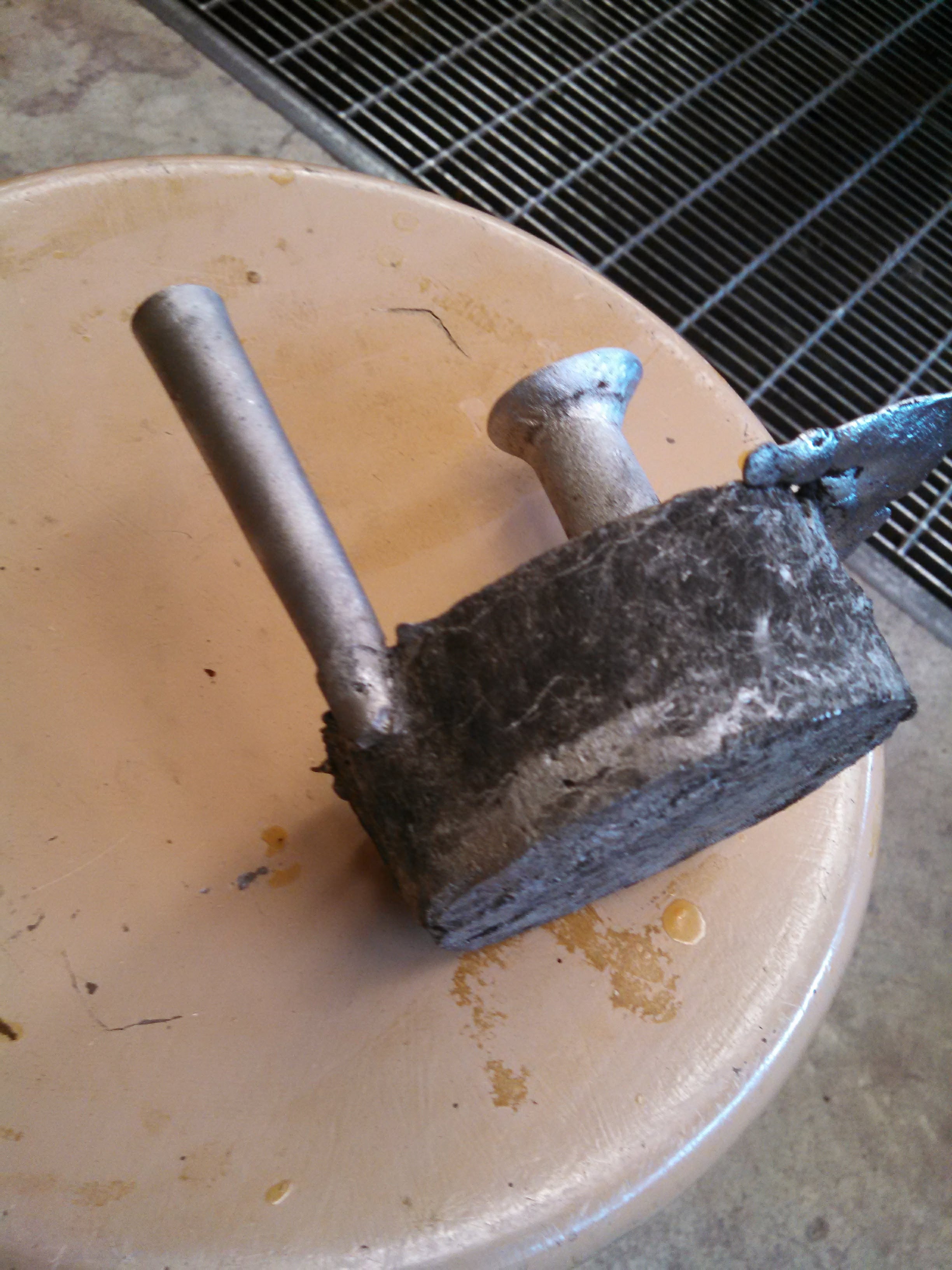
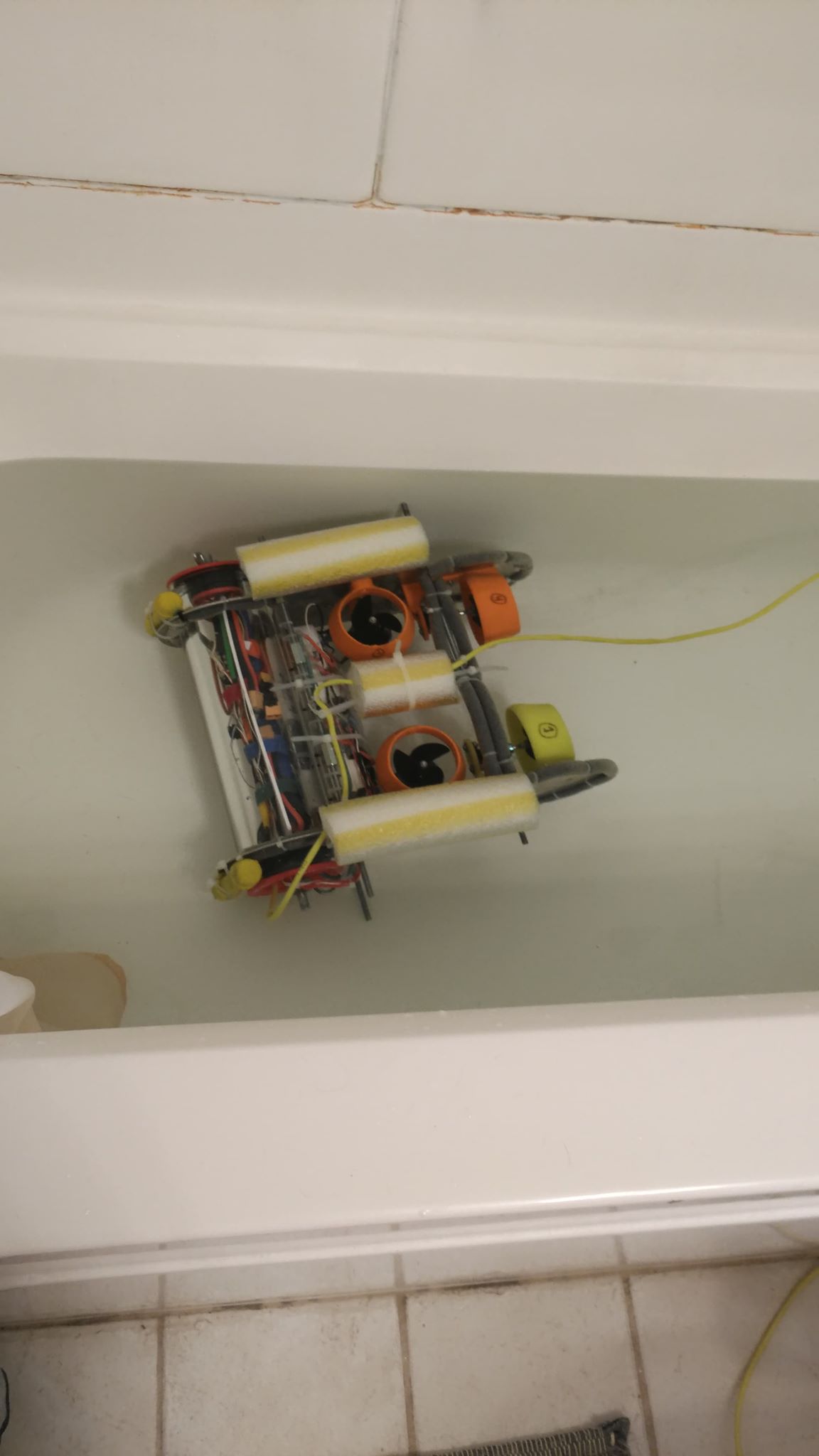
I had originally planed to use bilge-pump motors. This had two issues: first, bilge pump motors seize under pressure, and secondly, there were no readily available adapters to mount propellers. At this time I have no access to a machine shop to manufacture my own. Luckily the motors I purchased have threaded shafts. The propellers are mounted on the motor shaft as an assembly of four parts in this order: Locknut-Propellor-Modified Wingnut-Locknut Originally the wingnut was omitted, but the propeller would slip on the shaft at high speeds. Most of the wingnut’s ‘wings’ have been removed so that the propeller will sit flush against the nut. the remaining wings sit in slots in the propeller.

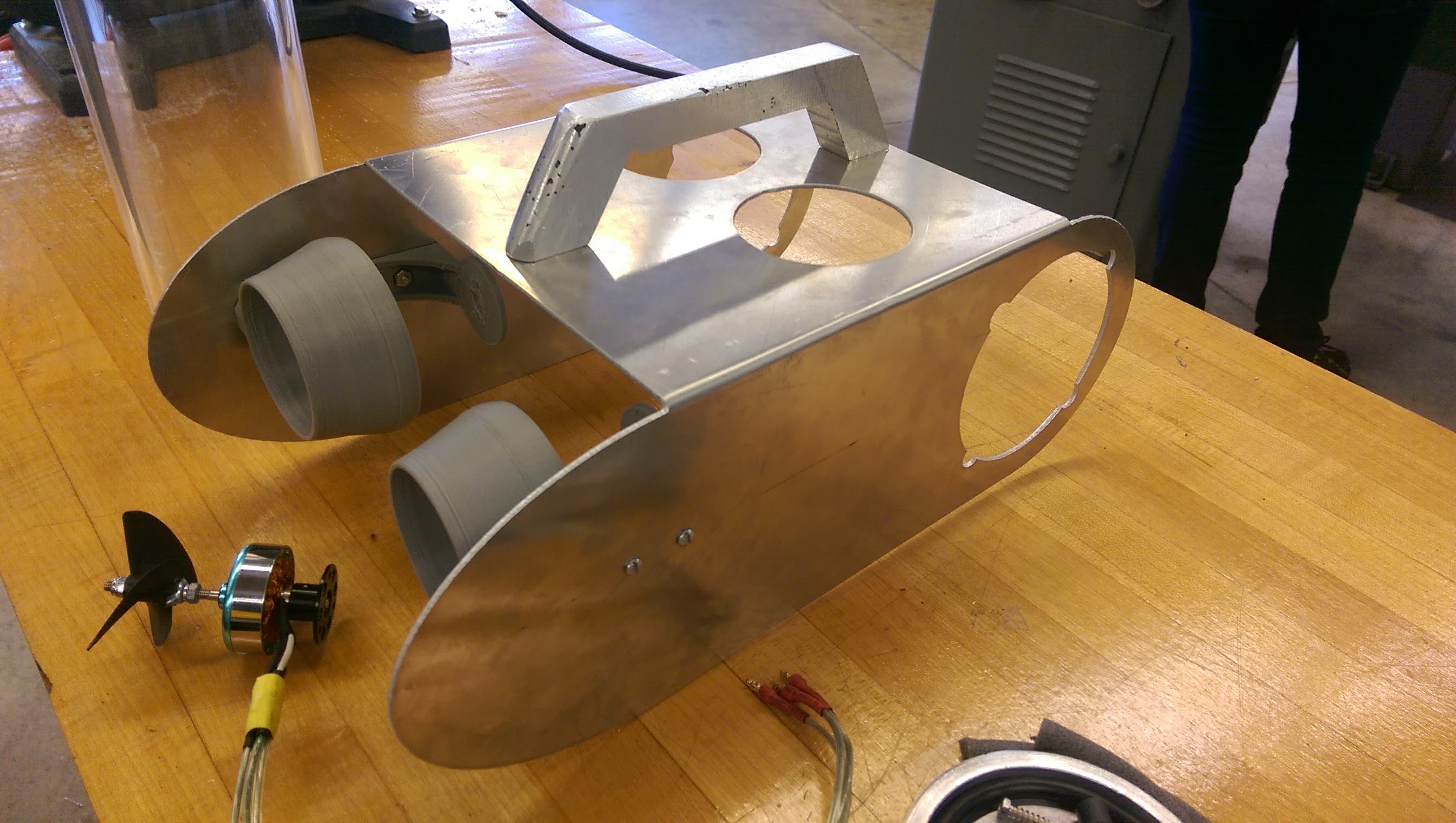
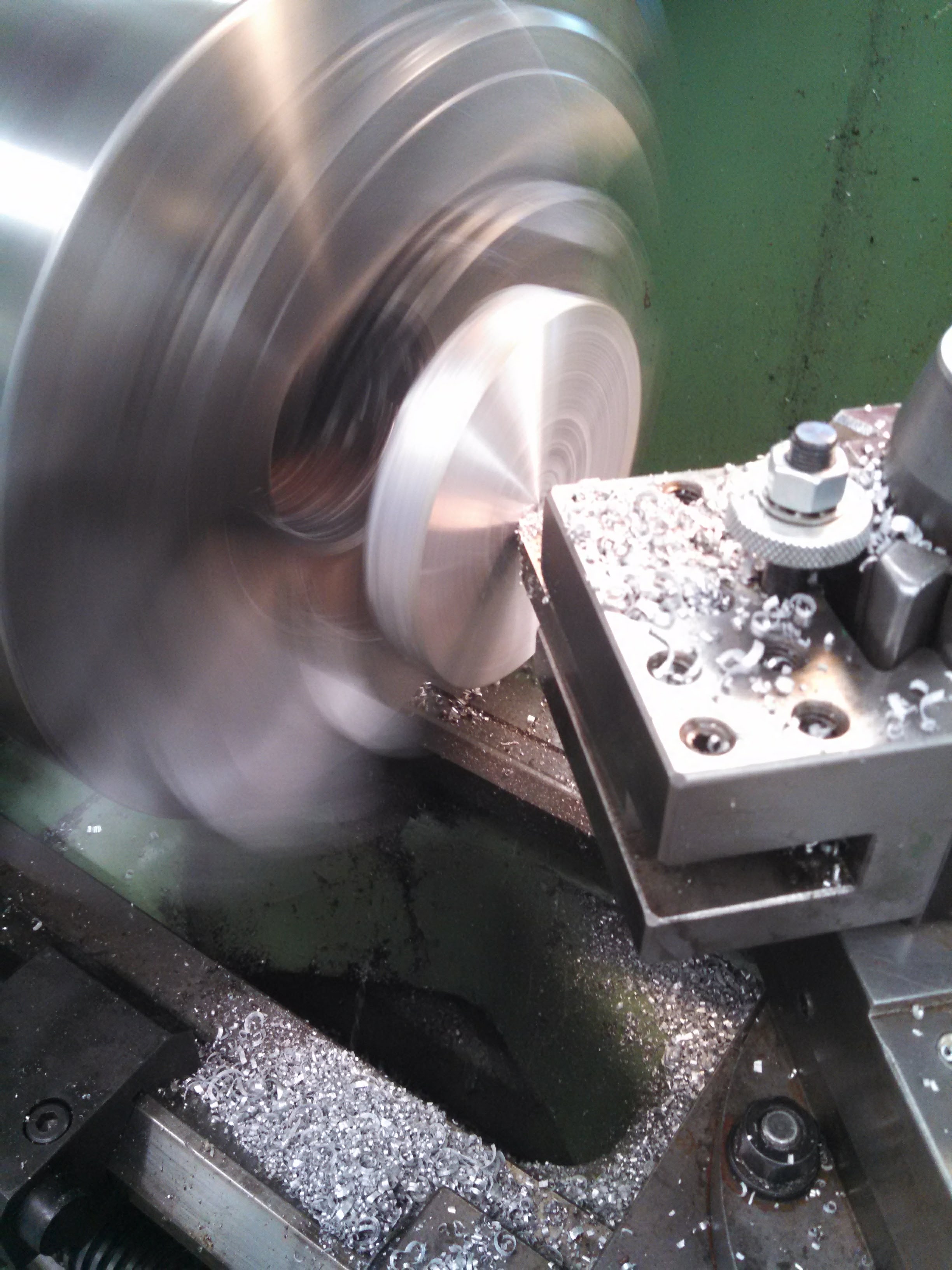
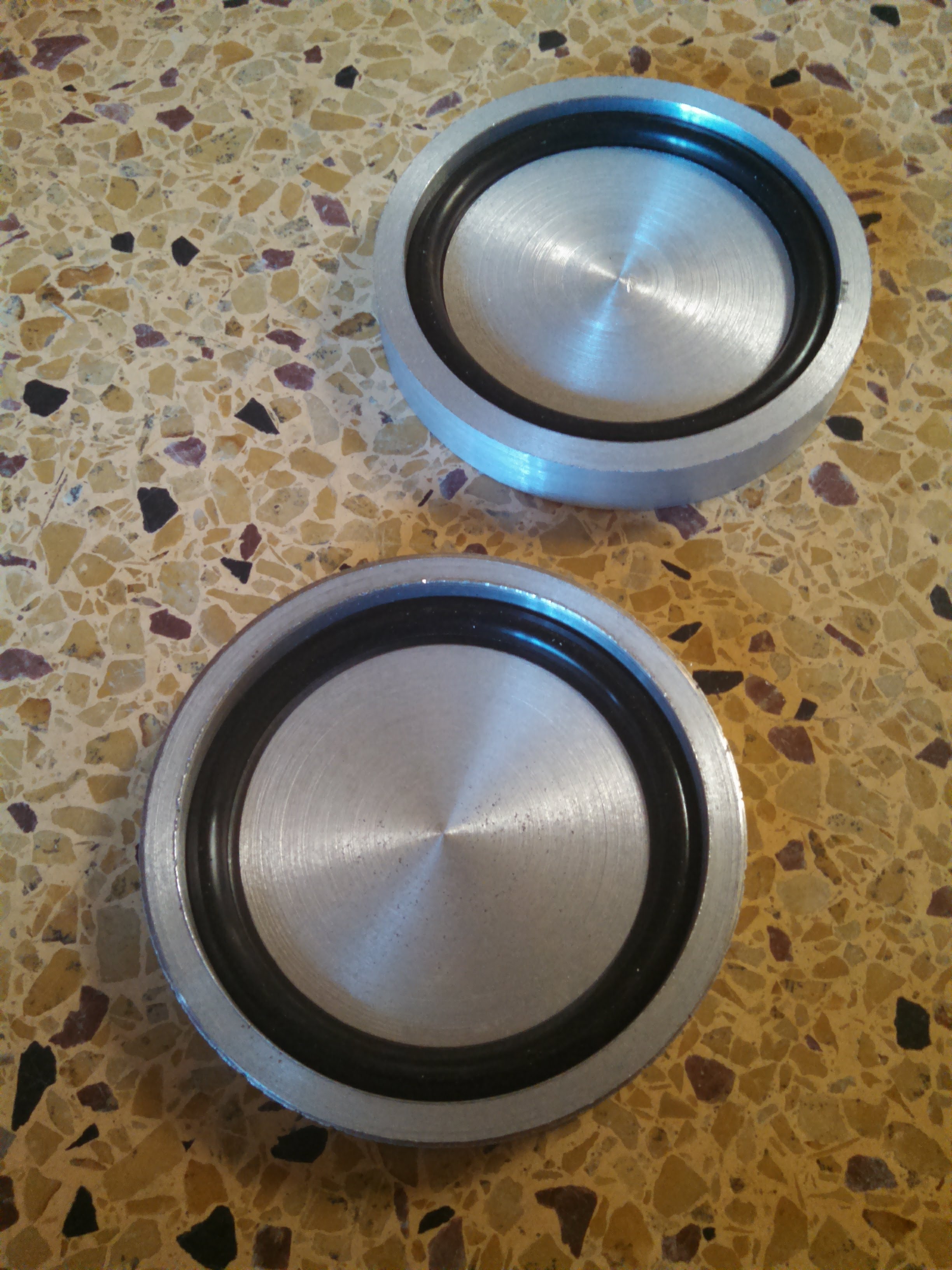
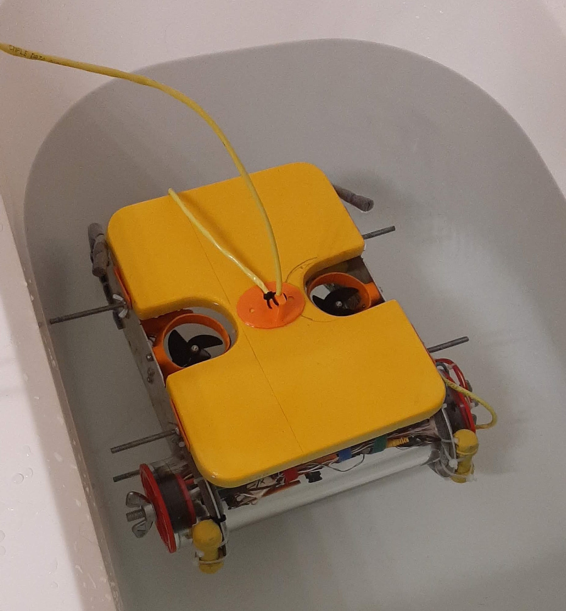
I’ve plasma cut and formed my frame, I’ve machined a handle, currently working on getting that mounted. My O-rings for my endcaps showed up today, Along with that, I’m still working on the actual machining of the endcaps. I’m still working on the motor mount designs, and an idea to get my ESC’s out of my housing


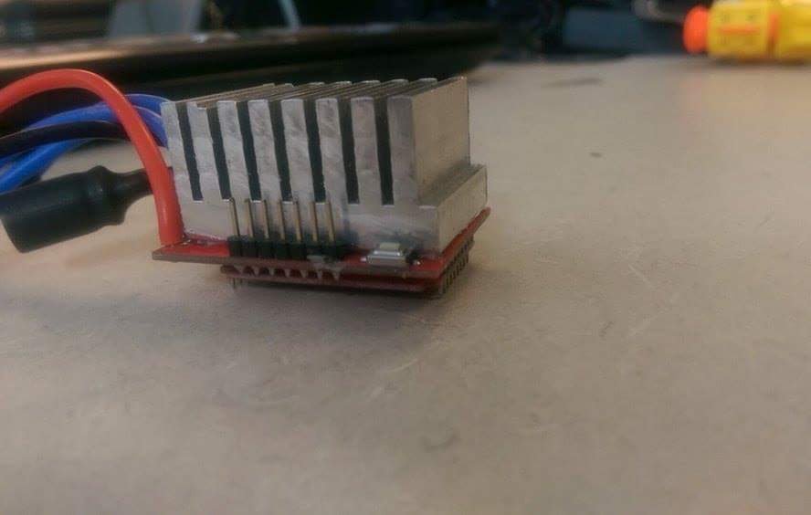
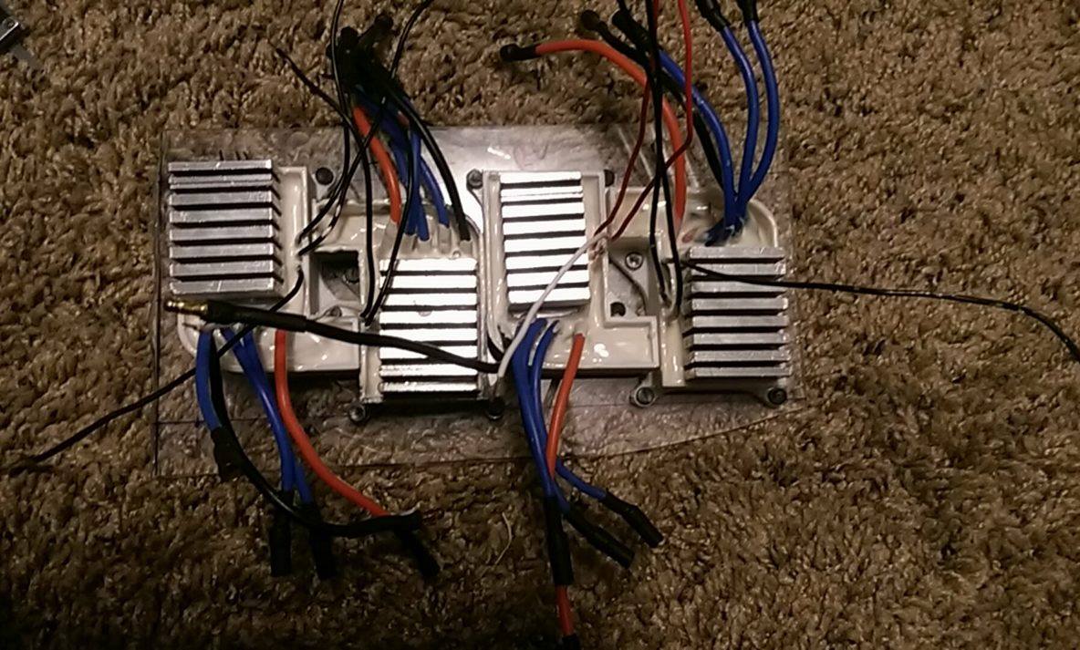
Basically pot the ESC and machine a longer heatsink that sticks into the water flow.